Smart Home Development - Light Control#
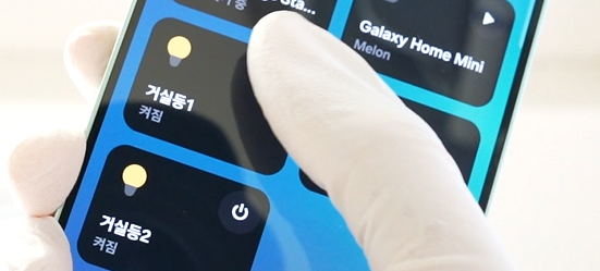
I have decided to create my own smart home system that lets you turn lights on and off with your phone.
This system would offer a variety of convenient features:
- Turning lights on and off from bed with your phone
- Turning off lights remotely when you forget and leave them on while going out
- Automatically turning off all lights at midnight
- Automatically turning on lights at 7am
- Automatically turning on lights when you enter the house after being out
- Automatically turning off lights when the house is empty
Just imagining it sounds incredibly convenient.
Check Wallpad#
I first checked the Wallpad.
My home’s Wallpad does not support Smart home features.
However, I can turn on and off the lights in the living room, kitchen, and each room through the Wallpad.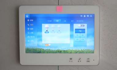
What does it mean that you can control the lights from the Wallpad?
It means that each light switch communicates with the Wallpad.
Therefore, if you can inject packets that can control the lights into the communication line, then it will be possible to control the lights.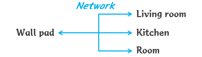
According to my research on the internet, most apartments in Korea use RS485 communications.
RS485 is made up of simple protocols, so it is likely that packets can be easily injected into the network (hereafter referred to as RS485 Bus).
Let’s see if packet injection is possible.
Types of Communication and Checking Packets#
I purchased a USB to RS485 device to determine whether my home uses RS485 communication and if the packet complexity is manageable for analysis.
This device allows me to send and receive packets from the RS485 bus through my computer’s USB.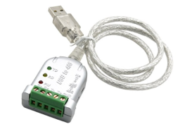
When you connect this device to a computer and install the drivers, it is recognized as a COM Port.
You can check in Device Manager to see if the device drivers are installed correctly and if the device is properly connected.
Depending on your computer’s configuration, the COM port number might be different, such as COM1, COM2, COM3, etc.
When connecting the device, make sure to identify which COM port appears and disappears upon disconnection.
You need to dismantle the Wallpad and connect it to the RS485 Bus.
To remove my home’s Wallpad, unscrew the bolts at the bottom, then lift the body upward to easily detach it.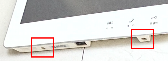
Behind the Wallpad, there were many wires, and it was complicated.
However, all I needed was to connect the RS485 Bus.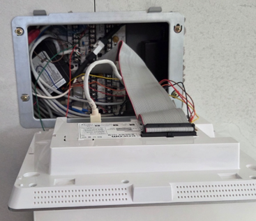
Upon closer examination, it appears that there are multiple terminals for connecting RS485.
I connected to one of the vacant RS485 terminals.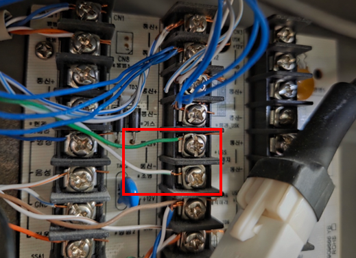
I also used a tool that could send and receive communication packets.
You can find various free tools for serial communication by searching on Google.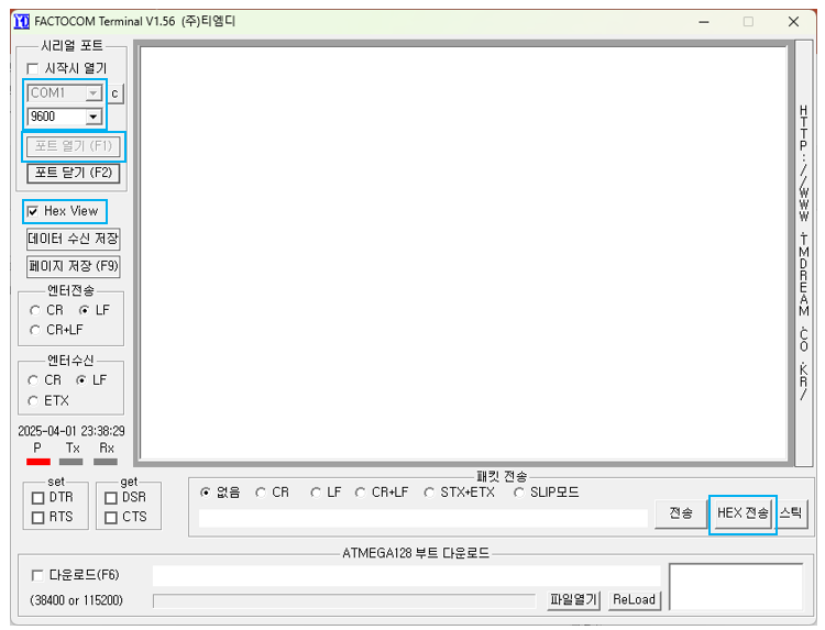
In Korea, the Baud rate for apartments varies, but it is mostly set to 9600.
I have also configured my settings to a Baud rate of 9600.
I connected to the RS485 Bus using a USB to RS485 device and opened the port.
When I press the light switches in the kitchen, room, and living room,
I can see that packets are being received, as shown in the following example.
When I repeatedly turned the light switch on and off, I noticed a consistent pattern in the communication packets.
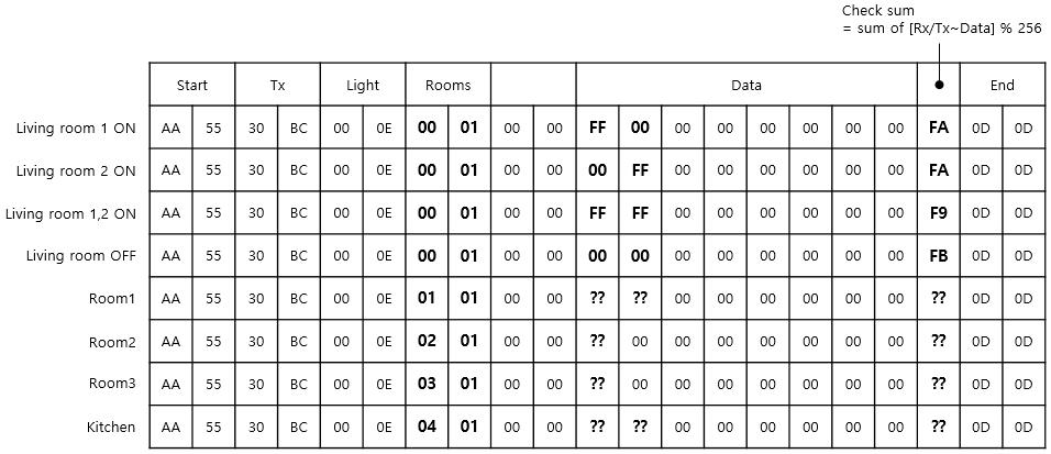
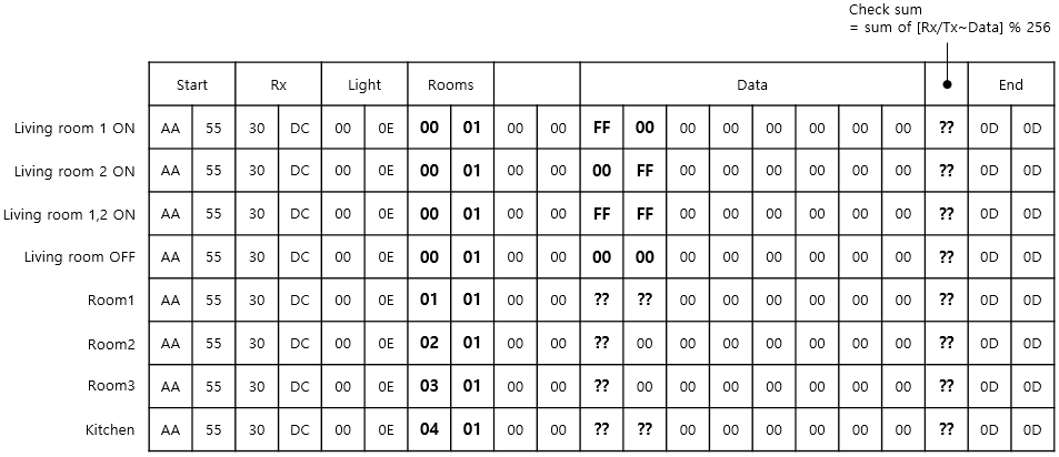
By analyzing these packets, I found that the method to turn the light on and off is as detailed in the following table:
The contents of the table are in Hex.
(1) Packet to turn the light on and off
(2) Packet for checking if the light is on or off
I used a tool that can send/receive communication packets to inject the packets described in (1) Sending Packets.
When I injected the packet to turn on the light, it switched on successfully.
When I injected the packet to turn off the light, it switched off successfully.
Also, when I pressed the light switches in each room, the packets described in (2) Receiving Packets were received.
This allowed me to determine whether the lights in each room were on or off.
I discovered that it is possible to control the lighting using packet injection on the RS485 Bus.
Develop with Arduino Nano Matter Board#
Now, let’s make a smart home by setting up the hardware.
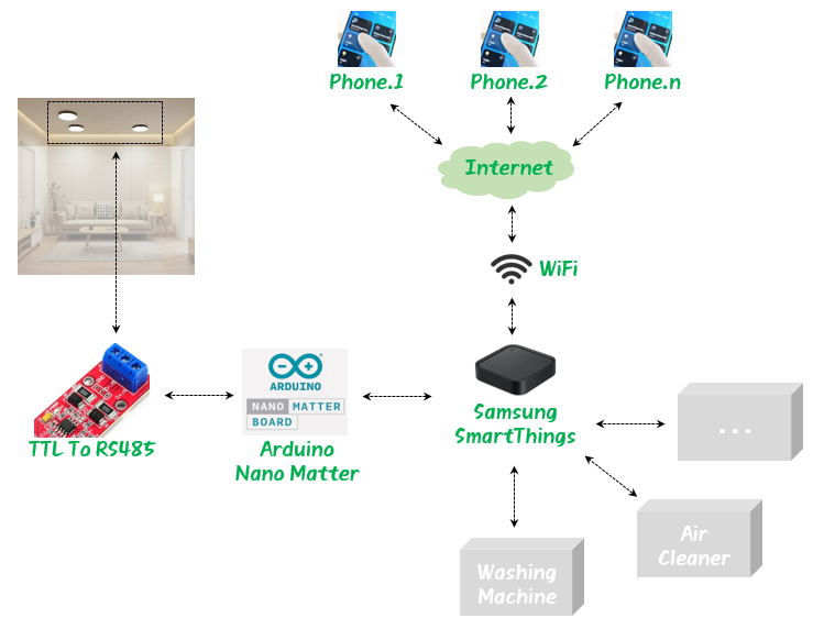
I used the existing WIFI router that was already in use at home and purchased the following three devices.
- Samsung SmartThings: Acts as a smart home Hub connecting various devices in the home with a smartphone.
- Arduino Nano Matter: Serves as an intermediary connecting SmartThings to an RS485 Bus.
- TTL To RS485: Converts Nano Matter’s Uart TTL levels to RS485 levels.
The overall system was configured as shown in the following figure.
SmartThings, manufactured by Samsung Electronics, is a finished product.
Therefore, you can install and use it by referring to the manual.
The Arduino Nano Matter board is not a finished product.
Therefore, you must program it yourself to determine how it will function.
I have attached the source code I wrote at the bottom of this post for your reference.
Compile the source code using the Arduino IDE and upload it to the Nano Matter device.
Once the upload is complete, open the Tools -> Serial Monitor function from the top menu of the Arduino IDE.
You will see a window at the bottom of the IDE where you can check the logs of the Nano Matter device.
Next, press the Reset button on the Nano matter board to restart the device.
When you check the logs, it provides the Paring code which is essential for connecting with SmartThings.
This Paring code is the unique device number of the Nano matter board.
Make sure to write it down as it is necessary when connecting the Nano matter board to your Phone through SmartThings.
Matter device is not commissioned
Commission it to your Matter hub with the manual pairing code or QR code
Manual pairing code: 12345678912
QR code URL: https://project-chip.github.io/connectedhomeip/qrcode.html?data=MT%ABCDEFGHIJKLMN
As you can see from the source code below, communication packets are transmitted and received via Serial1.
On the Nano matter board, the Serial1 pins are the UART1 Port (D0, D1 Pin).
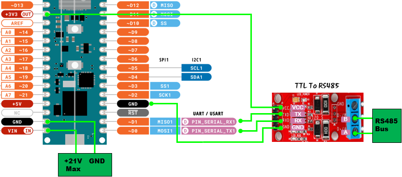
The voltage level output at D0 and D1 pins is TTL, which is not compatible with the voltage level on the RS485 Bus. Therefore, a TTL to RS485 converter is required to match the voltage levels.
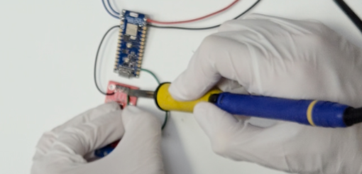
In the following diagram, the red board is the TTL to RS485 converter.
Refer to the green lines in the diagram to connect the Nano matter board with the TTL to RS485 converter (VCC, GND, RX, TX).
Install Hardware#
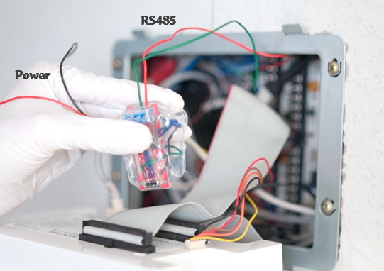
Connect the TTL to RS485 device to your home’s RS485 Bus as shown in the diagram below.
(Remove the USB to RS485 device that was used to check packets and connect it there.)
Finally, the power cable must be connected.
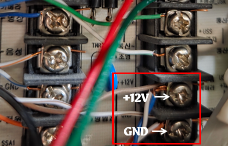
The VIN Pin of the Nano matter board can accept up to +21V.
As shown in the following diagram, the communication terminal at the back of the Wallpad is providing +12V, so it has been connected there.
This completes the installation.
Connect to Phone#
Press the Reset button on the Nano matter board to restart the device.
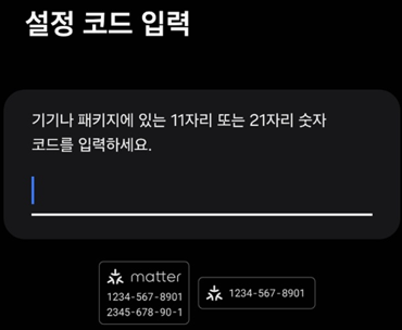
Then, register the device with your smartphone using the Paring code.
Now you can control the lights in your house with your Phone.
It’s very convenient !
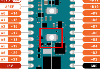
If you want to unpair on the Nano matter board, press and hold the following button for more than 5 seconds.
The LED will blink several times to indicate that the pairing has been released.
Refer to the source code below for the part that unpairs.
Code (Arduino Nano Matter)#
#ifndef LED_BUILTIN_1
#define LED_BUILTIN_1 PA0
#endif

#define DATA_SIZE      (21)

#define PACKET_START1  (0xAA)
#define PACKET_START2  (0x55)
#define PACKET_END1    (0x0D)
#define PACKET_END2    (0x0D)

#define LIVINGROOM     (0x0001)
#define ROOM1          (0x0101)
#define ROOM2          (0x0201)
#define ROOM3          (0x0301)
#define KITCHEN        (0x0401)


#include <Matter.h>
#include <MatterLightbulb.h>


MatterLightbulb device_livingroom_1;
MatterLightbulb device_livingroom_2;
MatterLightbulb device_kitchen_1;
MatterLightbulb device_kitchen_2;
MatterLightbulb device_room1_1;
MatterLightbulb device_room1_2;
MatterLightbulb device_room2;
MatterLightbulb device_room3;


bool status_livingroom_1 = false;
bool status_livingroom_2 = false;
bool status_kitchen_1 = false;
bool status_kitchen_2 = false;
bool status_room1_1 = false;
bool status_room1_2 = false;
bool status_room2 = false;
bool status_room3 = false;


void setup()
{
  Serial.begin(115200);
  Serial1.begin(9600);
  Matter.begin();

  device_livingroom_1.begin();
  device_livingroom_2.begin();
  device_kitchen_1.begin();
  device_kitchen_2.begin();
  device_room1_1.begin();
  device_room1_2.begin();
  device_room2.begin();
  device_room3.begin();

  pinMode(LED_BUILTIN, OUTPUT);
  digitalWrite(LED_BUILTIN, LED_BUILTIN_INACTIVE);
  pinMode(LED_BUILTIN_1, OUTPUT);
  digitalWrite(LED_BUILTIN_1, LED_BUILTIN_INACTIVE);

  pinMode(BTN_BUILTIN, INPUT_PULLUP);

  Serial.println("Matter multiple lightbulbs");

  if (!Matter.isDeviceCommissioned()) {
    Serial.println("Matter device is not commissioned");
    Serial.println("Commission it to your Matter hub with the manual pairing code or QR code");
    Serial.printf("Manual pairing code: %s\n", Matter.getManualPairingCode().c_str());
    Serial.printf("QR code URL: %s\n", Matter.getOnboardingQRCodeUrl().c_str());
  }
  while (!Matter.isDeviceCommissioned()) {
    delay(200);
  }

  Serial.println("Waiting for Thread network...");

  while (!Matter.isDeviceThreadConnected()) {
    delay(200);
    decommission_handler();
  }

  Serial.println("Connected to Thread network");
  Serial.println("Waiting for Matter device discovery...");

  while (
       !device_livingroom_1.is_online()
    || !device_livingroom_2.is_online()
    || !device_kitchen_1.is_online()
    || !device_kitchen_2.is_online()
    || !device_room1_1.is_online()
    || !device_room1_2.is_online()
    || !device_room2.is_online()
    || !device_room3.is_online()
  ) {
    delay(200);
    decommission_handler();
  }

  for (uint8_t i = 0u; i < 5u; i++) {
    digitalWrite(LED_BUILTIN, !(digitalRead(LED_BUILTIN)));
    delay(200);
  }
  digitalWrite(LED_BUILTIN, LED_BUILTIN_INACTIVE);

  Serial.println("Matter devices are now online");

  light_control(LIVINGROOM, false, false);
  delay(200);
  light_control(ROOM1, false, false);
  delay(200);
  light_control(ROOM2, false, false);
  delay(200);
  light_control(ROOM3, false, false);
  delay(200);
  light_control(KITCHEN, false, false);
  delay(200);

  device_livingroom_1.set_onoff(false);
  device_livingroom_2.set_onoff(false);
  device_room1_1.set_onoff(false);
  device_room1_2.set_onoff(false);
  device_room2.set_onoff(false);
  device_room3.set_onoff(false);
  device_kitchen_1.set_onoff(false);
  device_kitchen_2.set_onoff(false);

  serial1_buffer_clear();
}


void loop()
{
  decommission_handler();

  for (int i = 0; i < 128; i++)
  {
    refresh_light_status();
  }

  livingroom_handle();
  room1_handle();
  room2_handle();
  room3_handle();
  kitchen_handle();

  delay(1);
}


void serial1_buffer_clear()
{
    while (Serial1.available() > 0)
    {
        Serial1.read();
    }
}


unsigned char get_checksum(unsigned char* data)
{
  int sum = 0;
  for (int i = 0; i < 16; i++)
  {
    sum += data[i];
  }
  return sum % 256;
}


unsigned short read_rx_buffer(bool* light_1, bool* light_2)
{
  *light_1 = false;
  *light_2 = false;
  unsigned char rx[DATA_SIZE] = {0,0,0,0,0, 0,0,0,0,0, 0,0,0,0,0, 0,0,0,0,0, 0};
  int idx = 0;
  bool packetReceived = false;
  while (Serial1.available() > 0)
  {
    delay(2);
    unsigned char onebyte = Serial1.read();

    if (idx == 0 && onebyte == PACKET_START1)
    {
      rx[idx++] = onebyte;
      continue;
    }
    if (idx == 1 && rx[idx-1] == PACKET_START1 && onebyte == PACKET_START2)
    {
      rx[idx++] = onebyte;
      continue;
    }
    if (idx == DATA_SIZE-2 && onebyte == PACKET_END1)
    {
      rx[idx++] = onebyte;
      continue;
    }
    if (idx == DATA_SIZE-1 && rx[idx-1] == PACKET_END1 && onebyte == PACKET_END2)
    {
      rx[idx++] = onebyte;
      if (get_checksum(&rx[2]) != rx[18])
      {
        Serial.println("Checksum error");
        return 0x00;
      }
      Serial.println("Packet received");
      packetReceived = true;
      break;
    }
    if (idx >= 2 && idx < DATA_SIZE)
    {
      rx[idx++] = onebyte;
      continue;
    }
  } // while end

  if (packetReceived)
  {  // AA55 30DC 000E SITE 0000 DATA
    if (rx[2] != 0x30 || rx[3] != 0xDC ||
        rx[4] != 0x00 || rx[5] != 0x0E ||
        rx[8] != 0x00 || rx[9] != 0x00)
    {
      return 0x00;
    }
    if (rx[10] == 0xFF)
    {
      *light_1 = true;
    }
    if (rx[11] == 0xFF)
    {
      *light_2 = true;
    }
    if ( (((unsigned short)rx[6])<<8 | rx[7]) == LIVINGROOM )
    {
      return LIVINGROOM;
    }
    else if ( (((unsigned short)rx[6])<<8 | rx[7]) == ROOM1 )
    {
      return ROOM1;
    }
    else if ( (((unsigned short)rx[6])<<8 | rx[7]) == ROOM2 )
    {
      return ROOM2;
    }
    else if ( (((unsigned short)rx[6])<<8 | rx[7]) == ROOM3 )
    {
      return ROOM3;
    }
    else if ( (((unsigned short)rx[6])<<8 | rx[7]) == KITCHEN )
    {
      return KITCHEN;
    }
  }

  return 0x00;
}


void refresh_light_status()
{
  bool light_1, light_2;
  unsigned short site = read_rx_buffer(&light_1, &light_2);
  if (site == LIVINGROOM)
  {
    Serial.println("from Living room");
    device_livingroom_1.set_onoff(light_1);
    device_livingroom_2.set_onoff(light_2);
    status_livingroom_1 = light_1;
    status_livingroom_2 = light_2;
  }
  else if (site == ROOM1)
  {
    Serial.println("from Main room");
    device_room1_1.set_onoff(light_1);
    device_room1_2.set_onoff(light_2);
    status_room1_1 = light_1;
    status_room1_2 = light_2;
  }
  else if (site == ROOM2)
  {
    Serial.println("from Room2");
    device_room2.set_onoff(light_1);
    status_room2 = light_1;
  }
  else if (site == ROOM3)
  {
    Serial.println("from Room3");
    device_room3.set_onoff(light_1);
    status_room3 = light_1;
  }
  else if (site == KITCHEN)
  {
    Serial.println("from Kitchen");
    device_kitchen_1.set_onoff(light_1);
    device_kitchen_2.set_onoff(light_2);
    status_kitchen_1 = light_1;
    status_kitchen_2 = light_2;
  }
}


void decommission_handler()
{
  if (digitalRead(BTN_BUILTIN) != LOW || !Matter.isDeviceCommissioned()) {
    return;
  }
  uint32_t start_time = millis();
  while (digitalRead(BTN_BUILTIN) == LOW) {
    uint32_t elapsed_time = millis() - start_time;
    if (elapsed_time < 5000u) {
      yield();
      continue;
    }
    for (uint8_t i = 0u; i < 10u; i++) {
      digitalWrite(LED_BUILTIN, !(digitalRead(LED_BUILTIN)));
      delay(100);
    }
    Serial.println("Starting decommissioning process, device will reboot...");
    Serial.println();
    digitalWrite(LED_BUILTIN, LED_BUILTIN_INACTIVE);
    Matter.decommission();
  }
}


void light_control(unsigned short site, bool light_1, bool light_2)
{
  //AA55  30BC  000E  0001  0000  0000000000000000  FB  0D0D
  unsigned char tx[DATA_SIZE] = {0xAA,0x55, 0x30,0xBC, 0x00,0x0E, 0x00,0x01, 0x00,0x00, 0x00,0x00,0x00,0x00,0x00,0x00,0x00,0x00, 0xFF, 0x0D,0x0D};
  tx[6] = site>>8;
  tx[7] = site;
  if (light_1)
  {
    tx[10] = 0xFF;
  }
  if (light_2)
  {
    tx[11] = 0xFF;
  }
  tx[18] = get_checksum(&tx[2]);

  Serial1.write(tx, sizeof(tx));
  delay(200);
  serial1_buffer_clear();
}


void livingroom_handle()
{
  bool light_1 = device_livingroom_1.get_onoff();
  bool light_2 = device_livingroom_2.get_onoff();
  if (status_livingroom_1 != light_1 || status_livingroom_2 != light_2)
  {
    status_livingroom_1 = light_1;
    status_livingroom_2 = light_2;
    light_control(LIVINGROOM, light_1, light_2);
    Serial.println("Light control : LIVINGROOM");
  }
}

void room1_handle()
{
  bool light_1 = device_room1_1.get_onoff();
  bool light_2 = device_room1_2.get_onoff();
  if (status_room1_1 != light_1 || status_room1_2 != light_2)
  {
    status_room1_1 = light_1;
    status_room1_2 = light_2;
    light_control(ROOM1, light_1, light_2);
    Serial.println("Light control : ROOM1");
  }
}

void room2_handle()
{
  bool light_1 = device_room2.get_onoff();
  if (status_room2 != light_1)
  {
    status_room2 = light_1;
    light_control(ROOM2, light_1, false);
    Serial.println("Light control : ROOM2");
  }
}

void room3_handle()
{
  bool light_1 = device_room3.get_onoff();
  if (status_room3 != light_1)
  {
    status_room3 = light_1;
    light_control(ROOM3, light_1, false);
    Serial.println("Light control : ROOM3");
  }
}

void kitchen_handle()
{
  bool light_1 = device_kitchen_1.get_onoff();
  bool light_2 = device_kitchen_2.get_onoff();
  if (status_kitchen_1 != light_1 || status_kitchen_2 != light_2)
  {
    status_kitchen_1 = light_1;
    status_kitchen_2 = light_2;
    light_control(KITCHEN, light_1, light_2);
    Serial.println("Light control : KITCHEN");
  }
}